


Page 90 - Spindelhubgetriebe
P. 90
2   HUBGETRIEBE | KUGELGEWINDE | R-VERSION


                                GSZ 2 bis 25 kN
               KGT  KGT
                                KGT-R  |  Rotierende Spindel


               Nutzlänge=  Hub+Mutter
                                               Spindellänge  Einbauhöhe


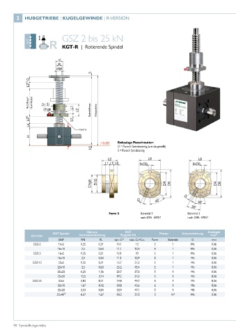
                                         Form E


                                                            Einbaulage Flanschmutter:
                                                            G = Flansch Getriebeseitig (wie dargestellt)
                                                            S = Flansch Spindelseitig


                                                        Form S          Bohrbild 1              Bohrbild 2
                                                                        nach DIN  69051         nach DIN  69051


                            KGT Spindel      Hub pro            KGT              Mutter      Schmierbohrung  Axialspiel
                 Getriebe                Antriebsumdrehung    Tragzahl kN                                  max 5)
                               ØxP        RN       RL      dyn. C 2)  stat. Co=Coa  Form  Bohrbild  G       mm
                  GSZ-2       16x5        1,25     0,31     10,1     12        E        1        M6         0,06
                              16x10       2,5      0,63     11,1     12,9      E        1        M6         0,06
                  GSZ-5       16x5        1,25     0,31     10,1     12        E        1        M6         0,06
                              16x10       2,5      0,63     11,1     12,9      E        1        M6         0,06
                 GSZ-10       25x5        1,25     0,31     13,7     21,5      E        1        M6         0,06
                              25x10       2,5      0,63     25,2     45,4      E        1        M6         0,06
                              25x25       6,25     1,56     20,7     37,3      E        1        M6         0,06
                              25x50       12,5     3,14     19,2     37,3      E        1        M6         0,06
                 GSZ-25       32x5        0,83     0,21     24,8     49,7      E        1        M6         0,06
                              32x10       1,67     0,42     30,8     45,6      E        1        M6         0,06
                              32x20       3,33     0,83     32,9     47,1      E        1        M6         0,06
                              32x40³⁾     6,67     1,67     18,3     37,3      S       N 4)      M6         0,06


        90  Spindelhubgetriebe

