


Page 37 - Gewindetriebe
P. 37
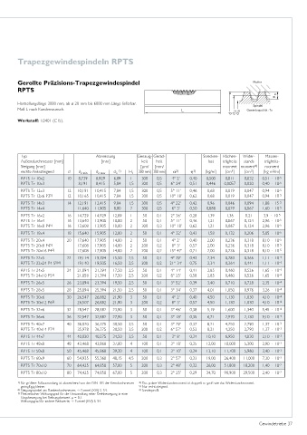
Trapezgewindespindeln RPTS


        Gerollte Präzisions-Trapezgewindespindel                                                   Mutter
        RPTS


        Herstellungslänge 3000 mm, ab ø 20 mm bis 6000 mm Länge lieferbar.                         Spindel
        Maß L nach Kundenwunsch.                                                                 Gewindequalität: 7e

        Werkstoff: 1.0401 (C15).


         Typ                          Abmessung       Genauig- Gerad-           Strecken-  Flächen-  Wider-  Massen-
         Außendurchmesser [mm]          [mm]            keit  heit                last  trägheits  stands  trägheits-
         Steigung [mm]                                  [µm/  [mm/                     moment moment 4)  moment
                                                                                           4
                                                                                                  3
                                                                                                           2
         rechts-/linkssteigend  d  d 2 min  d 2 max  d 3  1)  H 1  300 mm] 300 mm]  α 2)  η 3)  [kg/m]  [cm ]  [cm ]  [kg m /m]
         RPTS Tr 10x2      10  8,739  8,929  6,89   1   300   0,5   4° 2’  0,40  0,500  0,011   0,032  0,51 · 10 -5
         RPTS Tr 10x3          8,191  8,415  5,84  1,5  300   0,5  6° 24’  0,51  0,446  0,0057  0,020  0,40 · 10 -5
         RPTS Tr 12x3      12  10,191  10,415  7,84  1,5  300  0,5  5° 11’  0,46  0,68  0,019   0,047  0,94 · 10 -5
         RPTS Tr 12x6 P3 5)  12  10,165  10,415  7,84  1,5  300  0,5  10° 18’  0,62  0,68  0,019  0,047  0,94 · 10 -5
         RPTS Tr 14x3      14  12,191  12,415  9,84  1,5  300  0,5  4° 22’  0,42  0,96  0,046   0,094  1,88 · 15 -5
         RPTS Tr 14x4          11,640  11,905  8,80  2  300   0,5   6° 3’  0,50  0,888  0,029   0,067  1,60 · 10 -5
         RPTS Tr 16x2      16  14,729  14,929  12,89  1  50   0,1  2° 36’  0,28  1,39    1,36   0,21   3,9 · 10 -5
         RPTS Tr 16x4      16  13,640  13,905  10,80  2  50   0,1  5° 11’  0,46  1,21   0,067   0,124  2,96 · 10 -5
         RPTS Tr 16x8 P4 5)  16  13,608  13,905  10,80  2  300  0,3  10° 18’  0,62  1,21  0,067  0,124  2,96 · 10 -5
         RPTS Tr 18x4      18  15,640  15,905  12,80  2  50   0,1  4° 32’  0,43  1,58   0,132   0,206  5,05 · 10 -5
         RPTS Tr 20x4      20  17,640  17,905  14,80  2  50   0,1   4° 2’  0,40  2,00   0,236   0,318  8,10 · 10 -5
         RPTS Tr 20x8 P4 5)    17,608  17,905  14,80  2  200  0,2   8° 3’  0,57  2,00   0,236   0,318  8,10 · 10 -5
         RPTS Tr 20x16 P4 5)   17,608  17,905  14,80  2  200  0,2  15° 47’  0,71  2,00  0,236   0,318  8,10 · 10 -5
         RPTS Tr 22x5      22  19,114  19,394  15,50  2,5  50  0,1  4° 39’  0,43  2,34  0,283   0,366  1,11 · 10 -4
         RPTS Tr 22x24 P4 S 5)6)  19,140  19,505  16,50  2,5  200  0,2  21° 34’  0,75  2,34  0,364  0,441  1,11 · 10 -4
         RPTS Tr 24x5      24  21,094  21,394  17,50  2,5  50  0,1  4° 14’  0,41  2,85  0,460   0,526  1,65 · 10 -4
         RPTS Tr 24x10 P5 5)   21,058  21,394  17,50  2,5  200  0,2  8° 25’  0,58  2,85  0,460  0,526  1,65 · 10 -4
         RPTS Tr 26x5      26  23,094  23,394  19,50  2,5  50  0,1  3° 52’  0,39  3,40  0,710   0,728  2,35 · 10 -4
         RPTS Tr 28x5      28  25,094  25,394  21,50  2,5  50  0,1  3° 34’  0,37  4,01  1,050   0,976  3,26 · 10 -4
         RPTS Tr 30x6      30  26,547  26,882  21,90  3  50   0,1   4° 2’  0,40  4,50   1,130   1,030  4,10 · 10 -4
         RPTS Tr 30x12 P6 5)   26,507  26,882  21,90  3  200  0,2   8° 3’  0,57  4,50   1,130   1,030  4,10 · 10 -4
         RPTS Tr 32x6      32  28,547  28,882  23,90  3  50   0,1  3° 46’  0,38  5,19   1,600   1,340  5,45 · 10 -4
         RPTS Tr 36x6      36  32,547  32,882  27,90  3  50   0,1  3° 18’  0,35  6,71   2,970   2,130  9,10 · 10 -4
         RPTS Tr 40x7      40  36,020  36,375  30,50  3,5  50  0,1  3° 29’  0,37  8,21  4,250   2,790  1,37 · 10 -3
         RPTS Tr 40x14 P7 5)   35,978  36,375  30,50  3,5  200  0,2  6° 57’  0,53  8,21  4,250  2,790  1,37 · 10 -3
         RPTS Tr 44x7      44  40,020  40,275  34,50  3,5  50  0,1  3° 8’  0,34  10,10  6,950   4,030  2,10 · 10 -3
         RPTS Tr 48x8      48  43,468  43,868  37,80  4  100  0,1  3° 18’  0,35  12,00  10,000  5,300  2,90 · 10 -3
         RPTS Tr 50x8      50  45,468  45,868  39,30  4  100  0,1  3° 10’  0,34  13,10  11,700  5,960  3,40 · 10 -3
         RPTS Tr 60x9      60  54,935  55,360  48,15  4,5  200  0,3  2° 57’  0,33  19,00  26,400  11,000  7,30 · 10 -3
         RPTS Tr 70x10     70  64,425  64,850  57,00  5  200  0,3  2° 48’  0,32  26,00  51,800  18,200  1,40 · 10 -2
         RPTS Tr 80x10     80  74,425  74,850  67,00  5  200  0,3  2° 25’  0,29  34,70  98,900  29,500  2,40 · 10 -2
        1) Für größere Fußausrundung ist abweichend von der DIN 103 der Kerndurchmesser  4) Das polare Widerstandsmoment ist doppelt so groß wie das Widerstandsmoment.
         geringfügig kleiner.                          5) Nur rechtssteigend.
        2) Steigungswinkel am Flankendurchmesser;   Formel (XVI) S. 54.  6) Sonderprofil.
        3) Theoretischer Wirkungsgrad für die Umwandlung einer Drehbewegung in eine
         Längsbewegung bei Reibungsbeiwert µ = 0,1.
         Wirkungsgrad für andere Reibwerte;   Formel (XVI) S. 54.


                                                                                                     Gewindetriebe 37

