


Page 197 - Profilschienenführungen Kugelgewindetriebe Linearmodule
P. 197
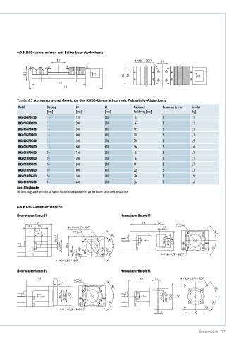
6.5 KK60-Linearachsen mit Faltenbalg-Abdeckung
6.5 KK60-Linearachsen mit Faltenbalg-Abdeckung 6.5 KK60-Linearachsen mit Faltenbalg-Abdeckung
53
53 53
52
52 52
L0
L1
L0
6.5 KK60-Linearachsen mit Faltenbalg-Abdeckung L0
6.5 KK60-Linearachsen mit Faltenbalg-Abdeckung
4×M6-18DP 41 L1 L1
4×M6-18DP 53 4×M6-18DP 41
41
6 2
6 5
6 2 52 6 2
6 5 6 5
L0
L1
4×M6-18DP
41
Tabelle 6.5 Abmessung und Gewichte der KK60-Linearachsen mit Faltenbalg-Abdeckung
Tabelle 6.5 Abmessung und Gewichte der KK60-Linearachsen mit Faltenbalg-Abdeckung
Tabelle 6.5 Abmessung und Gewichte der KK60-Linearachsen mit Faltenbalg-Abdeckung
Tabelle 6.5 Abmessung und Gewichte der KK60-Linearachsen mit Faltenbalg-Abdeckung Gewicht
Maximaler
L1
LO
Steigung
Modell
Reservehub L r [mm]
[mm] [mm] [mm] Modell Verfahrweg [mm]Steigung [kg] L1 Maximaler Reservehub L r [mm] Gewicht
Modell2 6 6 5 Steigung LO L1 Maximaler Reservehub L r [mm] LO Gewicht
35
KK6005P0150 5 [mm] 150 [mm] 220 [mm] Verfahrweg [mm] [mm] 5 [mm] 1,7 [kg] [mm] Verfahrweg [mm] [kg]
67 35
KK6005P0150 5 5 200 150 270 220 KK6005P0150 5 5 5 150 2,1 1,7 220 35 5 1,7
KK6005P0200
KK6005P0200 5 5 300 200 370 270 KK6005P0200 5 5 5 200 2,7 2,1 270 67 5 2,1
141 67
KK6005P0300
220 141
KK6005P0300 5 5 400 300 470 370 KK6005P0300 5 5 5 300 3,3 2,7 370 141 5 2,7
KK6005P0400
Tabelle 6.5 Abmessung und Gewichte der KK60-Linearachsen mit Faltenbalg-Abdeckung
KK6005P0400 5 5 500 400 570 470 KK6005P0400 5 5 5 400 3,9 3,3 470 220 5 3,3
290 220
KK6005P0500
Modell Steigung LO L1 Maximaler Reservehub L r [mm] Gewicht
KK6005P0500 [mm] 600 500 670 570 KK6005P0500 5 5 5 500 4,6 3,9 570 290 5 3,9
5 5
366 290
KK6005P0600
[mm]
Verfahrweg [mm]
[kg]
[mm]
KK6005P0600 10 5 5 150 600 220 670 KK6005P0600 5 5 5 5 600 1,7 4,6 670 366 5 4,6
366
KK6010P0150
35
150
1,7
35
220
KK6005P0150
KK6010P0150 10 10 5 200 150 270 220 KK6010P0150 10 5 5 5 150 2,1 1,7 220 35 5 1,7
67 35
KK6010P0200
KK6005P0200
2,1
67
200
270
141 67
KK6010P0200 10 10 5 300 200 370 270 KK6010P0200 10 5 5 5 200 2,7 2,1 270 67 5 2,1
KK6010P0300
141
2,7
KK6005P0300
300
370
220 141
KK6010P0300 10 10 5 400 300 470 370 KK6010P0300 10 5 5 5 300 3,3 2,7 370 141 5 2,7
KK6010P0400
3,3
400
470
KK6005P0400
220
KK6010P0400 10 10 5 500 400 570 470 KK6010P0400 10 5 5 5 400 3,9 3,3 470 220 5 3,3
290 220
KK6010P0500
KK6005P0500
3,9
290
500
570
366 290
KK6010P0500 10 10 5 600 500 670 570 KK6010P0500 10 5 5 5 500 4,6 3,9 570 290 5 3,9
KK6010P0600
600
4,6
KK6005P0600
366
670
KK6010P0600 10 600 670 KK6010P0600 10 5 5 600 4,6 670 366 5 4,6
366
Anschlagkante
KK6010P0150
10
150
220
1,7
35
Anschlagkante Anschlagkante
Die Anschlagkante be ndet sich vom Motoransch betrachtet an der linken Seite der Linearachse.
Anschlagkante
10
200
270
KK6010P0200
Die Anschlagkante befindet sich vom Motorflansch betrachtet an der linken Seite der Linearachse. 67 5 2,1
Die Anschlagkante be ndet sich vom Motoransch betrachtet an der linken Seite der Linearachse.
Die Anschlagkante be ndet sich vom Motoransch betrachtet an der linken Seite der Linearachse.
KK6010P0300 10 300 370 141 5 2,7
KK6010P0400 10 400 470 220 5 3,3
6.6 KK60-Adapter ansche 500 570 290 5 3,9
6.6 KK60-Adapterflansche
KK6010P0500
10
6.6 KK60-Adapter ansche 600 670 6.6 KK60-Adapter ansche 5 4,6
KK6010P0600
366
10
Motoradapter ansch F0 Motoradapter ansch F1
Motoradapter ansch F0
Anschlagkante
Motoradapter ansch F0 Motoradapter ansch F1 Motoradapter ansch F1
59
Die Anschlagkante be ndet sich vom Motoransch betrachtet an der linken Seite der Linearachse. 59 10 PCD46
18,5 59 30,5 4–M4 × 0,7P × 8DP 59 10 3,5 59 10
59
15,5 PCD46 PCD46
18,5 30,5 4–M4 × 0,7P × 8DP 18,5 30,5 3,5 4–M4 × 0,7P × 8DP 45° 3,5
PCD40
9
15,5 45° 15,5 PCD40 45°
9 Ø6 h7 PCD40 9 +0 42 45° 45°
6.6 KK60-Adapter ansche 30° 45° Ø26,5 Ø30 +0,05 +0
Ø6 h7 Ø28 +0,03 +0 44,5 30° Ø6 h7 Ø26,5 Ø30 +0,05 +0 42 30° Ø26,5 Ø30 +0,05 42
45°
Ø28 +0,03
44,5
+0
Motoradapter ansch F0 Ø28 +0,03 +0 44,5 23 0,5 30° 30° 45° Motoradapter ansch F1 4–M4 × 0,7P × 10DP 30° 45° 45°
23
23
0,5
0,5
59 4-M3×0,5P×8DP 45° 59 10 4–M4 × 0,7P × 10DP 45° 4–M4 × 0,7P × 10DP
18,5 30,5 4–M4 × 0,7P × 8DP 3,5 PCD46
15,5 4-M3×0,5P×8DP 4-M3×0,5P×8DP
Motoradapter ansch F2 PCD40 Motoradapter ansch F3 45°
9
Motoradapter ansch F2
Motoradapter ansch F2 10Ø6 h7 45° Motoradapter ansch F3 +0 42 Motoradapter ansch F3
59 PCD45 30° 59 10 Ø26,5 Ø30 +0,05 4-M5×0,8P×10DP
Ø28 +0,03
+0
4-M5×0,8P×10DP
59 10 3,5 44,5 PCD45 59 59 10 10 PCD45 45° 59 10 4-M5×0,8P×10DP
3,5 23 0,5 30° 45° 45° 3,5 45° 45°
Ø36 +0,05
Ø26,5 Ø30 +0,05 +0 42 45° Ø26,5 4–M4 × 0,7P × 10DP 45° 45°
60
+0
50
4- +0 +0 +0,05
Ø26,5 M3×0,5P×8DP 45° Ø26,5 Ø26,5 Ø36 +0,05 Ø30 60 +0 42 50 45° Ø26,5 Ø36 +0,05 +0 60 50
Ø30 +0,05
42
Motoradapter ansch F2 4-M 3×0,5P ×10DP 45° Motoradapter ansch F3 45° 45° 45°
3 50
4-M5×0,8P×10DP
59 10 4-M 3×0,5P ×10DP 59 10 3 4-M 3×0,5P ×10DP 3 50
PCD45
3,5 50
29
KK-05-1-DE-2109-K 45° 45°
Ø26,5 Ø26,5 Ø36 +0,05 50
29
KK-05-1-DE-2109-K Ø30 +0,05 +0 42 KK-05-1-DE-2109-K +0 60 Linearmodule 197 29
45° 45°
4-M 3×0,5P ×10DP
3 50
KK-05-1-DE-2109-K 29

